


Application case 12: Cathode baking control system
Calciner burner device and control system
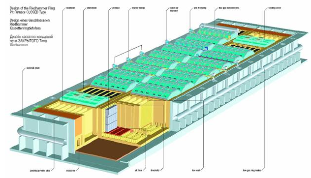
Room 24, with cover ring cathode baking, consists of two rows of 12 furnace chamber, an annular side main flue composition. Example diagram is as follows (in a 24-chamber two systems indicate)
Each system is equipped with stove 11-12 lid. Each lid has five burn holes for mounting the burner, and some observation hole for observing the temperature of various parts of the furnace chamber and the negative pressure.
Calciner burner and control system's role is working on the roaster oven chamber temperature and vacuum for effective control, so that in process requirements of the heating curve and the negative pressure within the scope of the carbon block bins products for pre-heat, baking and cooling; baking process and recording, storage, management, optimization control.
Furnace chamber lid 24 ring electrode configuration of two flame baking systems, each system is generally from 8 (can be extended to 9) in series furnace chamber cover cooling furnace chamber 3-4, a cooling furnace lid chamber. Furnace chamber system schematic is layout as follow in Fig1. The system is divided into the furnace chamber preheating zone (1P, 2P, 3P, 4P, 5P), calcination zone (6P, 7P, 8P or), cooling zone (9P, 10P, 11P, 12P) and other areas (for installed furnace, baked and maintenance and other operations).

The cold air from the furnace cover into the non-surface cooling furnace chamber, and the gap in the lattice material brick for heat exchange tank, the air preheated to 200 -400℃cooling furnace chamber into the cover, the same heat exchange, the air preheat to 800 -900℃after entering the furnace chamber, a gas injected into the combustion gases, gas combustion flue gas temperature will be raised to 1000 -1280℃; heating furnace back airflow into the main combustion chamber continues, gas burning heat insulation to maintain ; temperature flue gas before entering the furnace combustion chamber continues, gas fired heating flue gas temperature 830 -1280℃, and then flows into the late preheating furnace chamber, flue gas temperature 600 -830℃, continue to flow into the furnace chamber tar volatile period, flue gas temperature 350 -600℃, and finally into the preheated oven pre-chamber flue gas temperature of about 120 -350℃, the slope through the furnace chamber flue, Exhaust ramp flue into the main ring, after purification into the chimney, and then discharged into the atmosphere.
Directional flow of the flue gas in the furnace because of the indoor fan in the main ring-shaped negative pressure generated inside the flue , the flue gas by adjusting the degree of opening of the butterfly valve to control the size of the negative pressure ; the air flow faster ( higher vacuum ) in the unit length of the tobacco tract shorter cooling time , and thus the temperature drop in the preheating zone is smaller, the flow rate of the gas can be adjusted so as to control the heating rate of the furnace chamber .
System baking rack area located three sets of combustion FP1, FP2, FP3, each with five gas nozzles, respectively, to 5 fire gas injection wells, the corresponding furnace chamber for heating, simultaneous measurement of the temperature of the furnace chamber and the temperature control.
1 P on the downstream side of the preheating zone placed at the communicating portion flue cover ER1, 12 series of ventilation oven chamber, communicating the installation of the electric control valve housing, to adjust the control valve opening degree control of this series to adjust the negative pressure chamber of the furnace preheat oven chamber temperature. In the preheating zone of the furnace chamber temperature measurement devices placed inside the lid to measure the temperature of the preheated oven chamber
Degrees, the temperature signal corresponding to the control cabinet into the PLC, 1P signal into the control cabinet connected hood, 2, 3, 4, 5P signals into the signal acquisition cabinet, 6, 7, 8P signals into the line corresponding to the burning aircraft control cabinet. In 2P place a car used to measure pressure, measuring 2P negative pressure signal into the control cabinet connected hood. Through the field bus network will be the temperature of the furnace chamber to the host computer, and use these measurements for a full range of temperature after the operation , the negative pressure control , to ensure the negative pressure in the case of the set range , adjustment of the preheating furnace chamber preheat temperature curve .
After each heating process cycle, the flame combustion system moves along a furnace chamber.
Auxiliary burner frame in the process of production for the hood placed in close proximity to the second or third communication furnace chamber, for the realization of process curve. Therefore, at low temperature, the system of gas direct injection into the furnace chamber and will not burn, so the design of the air distribution and ignition with automatic detection and extinguishing a burner. To implement the products process requirements of temperature control of "two fast, intermediate slow". Heating the electrode in the low temperature region slightly faster rate, to ensure product does not change geometry.
Burning frame with pulse combustion, controlled by a solenoid valve of the gas injected into the well the amount of fire, combustion control. This kind of approach has uniform temperature combustion, combustion efficiency, and ease of automatic control advantages. This control of the combustion temperature at a constant frame rate of heating, insulation , and controls cooling to a certain rate , the temperature control of the oven chamber can be moved down to a certain temperature furnace, the furnace chamber into the cooling state.
Roaster automatic temperature control system is divided into six control subsystems: the furnace chamber temperature control subsystem 3 , preheat oven chamber negative pressure control subsystem 1 , preheating furnace chamber temperature control subsystem 1 , preheating zone air temperature control subsystem an aircraft fire .
2. System Functions
Calciner burner and control system has the following features:
● Achieve calcination zone (8P, 7P, 6P) and the preheating zone furnace automatic control of room temperature , to keep track corresponding to the curve zone temperature setting , so as to ensure the actual temperature profile of the furnace chamber firing process to meet the requirements.
● Implement a preheating zone (2P or 3P) automatic control of the furnace room temperature, to keep track corresponding to the curve zone temperature setting, so as to ensure the actual temperature profile of the furnace chamber firing process to meet the requirements.
●Through the preheating and heating zones, the temperature and pressure parameters for the collection and calculations, to achieve preheated negative pressure downstream of the outlet of the heating zone of the furnace chamber and the negative pressure control, so that the negative pressure operating range of the set and thus ensure the firing chamber and the preheating zone furnace firing process to meet the requirements of negative pressure.
●With safety interlock functions: a ) in the automatic control process, when the calcination zone flue gas temperature is lower than the gas ignition , the system sends an alarm signal and automatically shut down the combustion gas solenoid valve rack to prevent flameout jet ; 2 ) When the calcination zone furnace chamber furnace chamber temperature and set temperature value is greater than the absolute value of the difference between the allowable range , the system sends an alarm signal to determine the cause react accordingly in order to prevent gas solenoid valve mechanical failure caused the normally open jet ;
● Process control to achieve real-time data acquisition , storage, management, statistics , alarms , report generation and printing records ; historical curve and other management functions in accordance with the specific requirements of the proposed site process personnel requirements to achieve ;
● Control system uses centralized monitoring and management, distributed real-time control of two distributed real-time control system, improve system reliability and operation, ease of maintenance. System status display, alarm, parameter setting of the control subsystem and the remote control can be centralized in the control center. Meanwhile, the real-time control of the control subsystem independently in the field , and in the field of the control subsystem manual and automatic control operation ; furnace surface field control system can be run independently from the central system , and in the field of the control sub- station on the system parameters and control parameters setting and modification.
● System control, measurement, design requirements for the implementation of parts of the interface easy to replace, so that the component failure timely replacement parts module, ensure that the production process is not interrupted.
● The system has considerable fault diagnosis and localization of function: When the system component fails, the automatic control system should be able to timely alarm and indicate fault location (or component) and type for the system maintenance personnel for timely repair. All analog input signal system automatically determines and displays whether open or shorted.
● The system can be extended to 9 room operation mode, i.e. an increase in the combustion system burning frame, so that the furnace chamber temperature was increased to nine rooms, productivity.
3. System Configuration
Field bus control system uses the LAN communication, to achieve the scene between the control cabinet and their communication with the central connection between devices. The programmable controller (PLC) as a field core control unit adapts to the scene temperature, high dust and severe vibration environment, to ensure on-site real-time control subsystem reliability. Industrial Control using PC as the control center centralized monitoring computer , use PC-rich , flexible software development resources designed intuitive interface, easy to operate , high-performance centralized monitoring and management software , as well as ease of system operation control data published on plant-level LAN .
Roaster’s baking control system structure shown in Fig2. In the field of equipment (HR1, HR2, HR3, Pro-HR, SM, ER,) were set on measurement and control cabinet. All measurements and data signals through the control cabinet unified network interface to the related control cabinets and control centers, all control signals for closed-loop control in the field calculation output. The description of each subsystem is as following.
3.1. Exhaust ramp ER (negative control)
Exhaust rampcontrol cabinet mounted programmable logic controllers, complete Exhaust ramp at the air volume control valve automatic control, by adjusting the negative pressure outlet indirectly regulate the preheating zone furnace chamber temperature curve. System status and control information sent to the control center monitoring computer. Temperature element mounted in a preheating zone of the furnace chamber lid on the pressure measuring element is mounted on a movable trolley, testing 2P furnace chamber vacuum, temperature and pressure signal access Exhaust ramp control cabinet, through industrial Ethernet bus from signal measurement cabinet acquisition 3P, 4P, 5P temperature in the preheating zone of the negative pressure control. Human Interface Module using SIEMENS as a field man-machine interface set the manual, automatic and remote three modes of operations. Control parameters and manual operation can be set by the control center monitoring computer controlled man-machine interface module can also be configured in the field and control.
3.2. Auxiliary burner frame Pro-HR (auxiliary burner shelf controller)
Set an auxiliary combustion system rack, rack set in the auxiliary combustion auxiliary burner rack controller completes furnace chamber where temperature control , so that the flue gas temperature at furnace chamber group setting curve operation . System status and control information sent to the control center monitoring computer. Human Interface Module using SIEMENS as a field man-machine interface set the manual, automatic and remote three modes of operations. Control parameters and manual operation can be set by the control center monitoring computer controlled man-machine interface module can also be configured in the field and control.
Auxiliary burner rack placed in a 2P or 3P, via metal hoses and quick connectors connected to the gas pipeline with the workshop.
Secondary combustion gas into the frame , through the valve the pressure stabilized at about 0.5Kg , and then through the electric control valves, flow meters , each branch pipe , valve , solenoid valve , to reach the burner .
The air required for combustion auxiliary burner installed in the frame of the fan to provide , and then through the electric control valves, flow meters , each branch pipe , valve , reaches the gas burner was sufficiently mixed , and then into the furnace combustion chamber .
Gas and air mixture ratio, make settings on the control panel, the logic controller based on the instantaneous flow of gas and air to regulate their own electric control valve, controlled by combustion gas and air mixture ratio needed to enter the burner.
Since 2P, 3P furnace chamber temperature is below the ignition temperature of the gas temperature, gas into the furnace chamber does not burn, so auxiliary burner frame equipped with automatic ignition and fire detection.
3.3. Burning frame FP
Three combustion system setting frame , mounted in the combustion shelves shelf programmable logic controllers complete the combustion chamber where the furnace temperature control , so that the gas temperature of the oven chamber set at a set curve operation . System status and control information sent to the control center monitoring computer. Or control instrumentation devices using SIEMENS Human Interface Module as a field man-machine interface, set the manual, automatic and remote three modes of operations. Control parameters and manual operation can be set by the control center monitoring computer controlled man-machine interface module can also be configured in the field and control.
Burning rack placed in the 6P, 7P, 8P, via metal hoses and quick connectors connected to the gas pipeline with the workshop.
Holder into the combustion gas , through the valve the pressure stabilized at about 0.5Kg , and then through the electric control valves, flow meters , each branch pipe , valve , solenoid valve , to reach the burner .
As 6P, 7P, 8P furnace chamber temperature is higher than the ignition temperature of the gas temperature , gas into the furnace interior can burn, so the combustion burner frame not equipped with automatic ignition and fire detection.
3.4. Signal measurement and transmission cabinet SM
On each side of the system to set up a roaster signal measurement and transmission cabinets, shelves installed in the combustion of the standard programmable logic controller completes burning furnace temperature signal acquisition and transmission , and data transfer via Ethernet to the control center monitoring computer .
3.5. Centralized monitoring system control center
Centralized control center monitoring system installed in the main control room, by the IPC , large screen monitors, printers, Ethernet card , network switches form , completing the full roaster control system of centralized monitoring ( including system status display, alarm , each subsystem parameters settings, remote manual operation, etc. ) , process control process data collection and management ( including data collection, database creation operation , data statistics , historical data query , curves, and report generation and printing , etc. ) , fault diagnosis and localization ( real-time analysis of system performance data the system failure alarm or pre-alarm and indicate the location of faulty equipment or parts ) . System-created database running on the LAN can be opened in the factory level, for the production management decisions provide the raw data.
