

Application case 13: Flue gas purification of Cathode baking control system
Project Name: Tokai Carbon Plant Alcoa two cathode baking flue gas purification device monitoring system
Implementation Date: December 2003
Overview
Baking gas purification and anode cathode purification basically is the same in carbon factory, just more than a burning subsystem. Baking plant flue gas purification device is located at the end, including flue gas cooling subsystem, burning subsystem, subsystem cyclone, bag filter subsystem, alumina material handling subsystem and the negative pressure control subsystem. Not only cooling and purification the cathode baking gas and Compliance emissions in the realization, but also providing a stable cathode vacuum firing system, to ensure the normal operation of the cathode baking.
Flue gas cleaning system, automatic control system is to purify the production monitoring and control of the integrated control system for flue gas emissions in the process of flue gas temperature , pressure, flow and other data to monitor, control, Carbon Factory cathode firing system plays a crucial important role,
The process description
Come from the baking plant flue gas first enters the spray tower, atomized water spray tower through the flue gas is cooled, if the flue gas temperature is low, spray cooling tower without treatment, only the spray tower outlet flue gas temperature is high the set value, the atomized spray tower was cooled, when the flue gas temperature is below the set value, the cooling treatment is stopped atomization.
The cooled flue gas into the venturi reactor, the reaction with alumina, in the flue gas tar, asphalt particles adhered on the alumina powder. Alumina powder by a feed motor from the disk added to the hopper feed pipe, transported by the flow of the fan into the venturi reactor.
After the flue gas is fed into the reactor cyclone, cyclone dust collector of the harmful substances in the flue gas into the combustion incinerator. After combustion process flue gas re-enter the cooling tower.
The flue gas is fed into the bag filter after cyclone, bag filter dust from the 12 chambers. Alumina powder is collected by bag filter and after into the return duct returned into the back bunker by the lift fan. Cleaning Blowback control has three operating modes: manual, timing, and differential pressure.
Negative pressure,required for normal production by Baking plant, is provided by the cited wind turbines of purification system, the negative pressure is adjusted by adjusting the valve opening in fan inlet to achieve.
The control requirements
In order to ensure the normal operation of baking and emissions standards, requiring automatic control system for purifying device performs the following monitoring functions:
l Acquisition, monitoring flue gas inlet and spray tower outlet temperature changes according to the temperature conditions implemented spray, bypass , through fire and flood control ;
l Detection alumina material flow pipeline and promptly stop sending alarm information;
l Detection alumina silo material level, upper and lower alarm;
l Control of the electric valve action and detect the switch status, fault alarm information;
l Detection alumina flow and form a closed loop control of the feeder, the feeder speed controlled by an inverter;
l Detection bag filter pressure state, according to three modes (manual, timing, and differential) control dust cleaning process;
l Negative variation detecting gas inlet , and the fan inlet valve businesses form a closed loop control , the negative pressure to keep the set value of the error range ;
l The solid particle content in Detection flue gas flow is higher than the set value alarm.
Equipment selection and control scheme
According to the actual requirements of security for the system to function properly, all full selection of an instrument imported or joint venture products:
All pressures were detected by ABB's pressure and differential pressure transmitter;
Temperature detection is using ABB's platinum thermal resistance;
Material level is using K-TEK radar level gauge;
Flue gas flow is using Verabar;
Gas solids are using English general products.
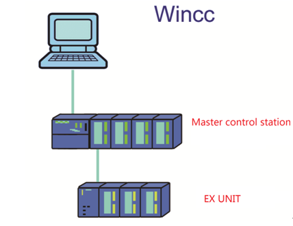
This system uses lower machine control system Siemens S7-300 series programmable controller (PLC), the central processor (CPU) using CPU315-2DP, using the interface module IM365 connected expansion I / O system can be extended communication speed.
PC system using industrial control machine as a man-machine interface, through the CP5611 communication card access Profibus-DP bus to communicate with the CPU, monitor software uses Siemens WinCC configuration monitoring software, multi-screen display system of the electric valve status, and monitor throughout the temperature and pressure changes.
Hardware configuration diagram is as follows:
Using Siemens STEP7 V5.0 programming software is programming. STEP7 is one pair of S7-300 and S7-400PLC programming application configuration package can program S7-300, 400PLC program that can handle more complex PID calculation, but also on -line monitoring of the program, the query failure.
The incinerator control scheme
1. The cathode purification incinerator Description: incinerator purification system of the cathode, by a certain proportion of heavy oil and air in the combustion incinerator, the incinerator flue gas through the baking, one of the flammable substance (bitumen and tar and some dust) burned away, out of the flue gas into the cooling tower and then go to the next unit.
☆ Incineration system consists of incinerators, oil gun, heavy oil combustion air piping and piping components.
☆ Incineration Hardware: 1 incinerator , 3 oil gun , combustion air blower 2 and 3 the combustion air control valve , a fuel oil control valve, the solenoid valve 3 atomization , three purge solenoid valve.
☆ Monitoring variables:
Analog: Heavy Traffic Heavy Traffic heavy pressure combustion air flow temperature incinerator
Digital: fans, solenoid valves, pressure switches
☆ System main parameters:
Heavy pressure: 2.5 ~ 3Kg/m2
Heavy Traffic: Maximum 60m3 / h
Heavy oil temperature: higher than 80℃
Combustion air flow: 730m3 / h
Incinerator temperature: 800℃ ~ 900℃
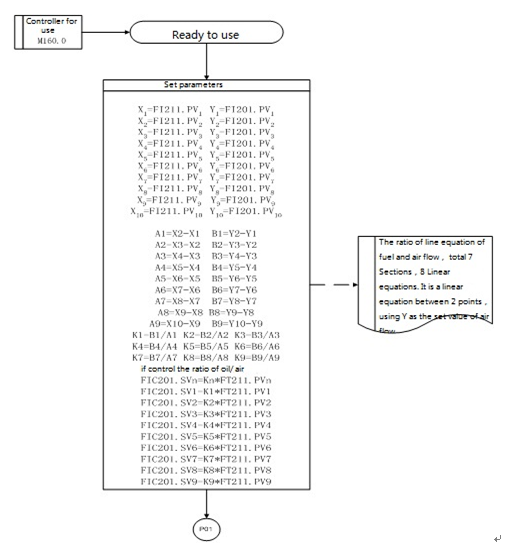
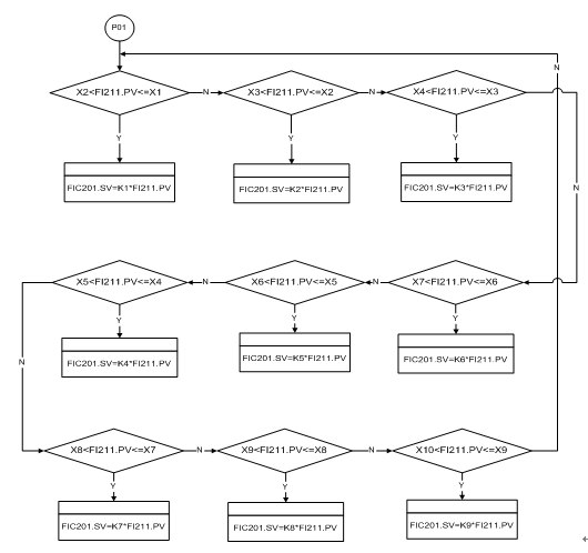
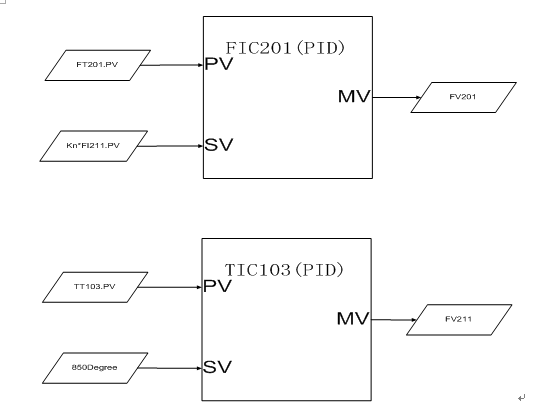
2. Incinerators control scheme:
System can manual ignition, automatic ignition, automatic adjustment the temperature of incinerator. By adjusting the flow rate and the combustion air flow rate of heavy oil to adjust the temperature of the incinerator, to maintain 800℃ ~ 900℃, where the PID control. With self -learning function control incinerator burning, can automatically adjust the temperature of the incinerator , based on pre- implantation learning points , heavy traffic or combustion air can flow gradually to the electrical near learning point adjustment , the final form the most appropriate way of proportioning . When heated, the first increase air flow, and then add oil; cool, first reduce the amount of oil, and then reduce the amount of wind. This enables the combustion of the best. System according to section incineration temperature combustion of heavy oil flow and air flow, and with heavy traffic increases and decreases, the system automatically closing and opening of the corresponding oil gun work. The actions are reliable and timely. System is automatic alarming, automatic recording temperature, pressure and other important parameters, and coming into formation, the system has reliable operation, friendly interface and simple operation.
Here is the control flow chart: